Most LED furniture projects fail not because of materials or lighting, but because designers overlook the fundamental physics behind rotational molding. In this article, you’ll master the 8 iron rules that prevent 95% of common production mistakes—plus discover the optimal specifications for LED channels and the design validation approach that can dramatically reduce mold modification costs.
The 8 Iron Rules of Rotational Molding Design
(Ordered by manufacturing difficulty)
2 cm Hollow Space Rule ⭐⭐⭐ — The #1 Failure Killer
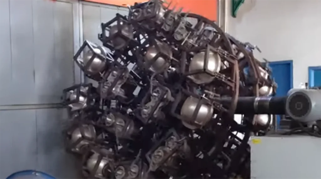
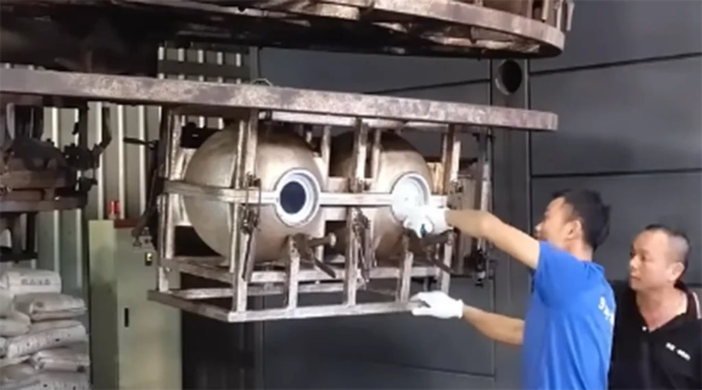
Powder Flow Principle:
During biaxial rotation, 0.3–1.2 mm polyethylene powder needs at least 2 cm of free space to roll and melt uniformly.
If the clearance is smaller, stagnant zones appear. Unmelted powder creates thin walls, pinholes, and weak spots.
Best Practice:
Keep 3–5 cm internal spacing in LED furniture. The extra gap improves powder flow, leaves room for LED strips, and helps with heat dissipation.
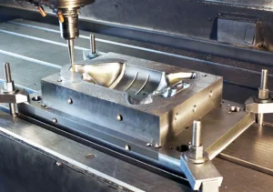
Post‑Processing Openings Principle ⭐⭐⭐ — The Cost Killer
All openings—lamp holes, drainage points, and nut seats—must be cut or drilled after molding. Never build them into the mold.
Reason:
Pre‑placed holes complicate parting lines, trap stress during heating, and cause flash or warping. They also shorten mold life.
Best Practice:
Use post‑processing (cutting, drilling, or CNC trimming) once parts cool. This approach typically reduces machining effort by 70–80% and allows flexible hole positioning.
Technical Insight:
Removing pre‑molded holes simplifies mold heating and cooling. It produces more stable wall thickness and accurate LED alignment for light channels and waterproof fittings.
H ≤ D Internal Cavity Rule ⭐⭐ — The Uniformity Killer
During rotation, the powder acts like sand. It settles at the bottom while a thin layer climbs the walls.
If the cavity is too deep, the top starves, and the bottom thickens.
Best Practice:
Keep depth equal to or less than diameter (H ≤ D).
For a 40 cm LED stool, limit internal depth to ≤ 38 cm.
Technical Insight:
The H ≤ D ratio balances powder coverage and heat exposure.
A deeper cavity leads to thin top walls, stress cracks, and weak joints—especially in translucent LED furniture.
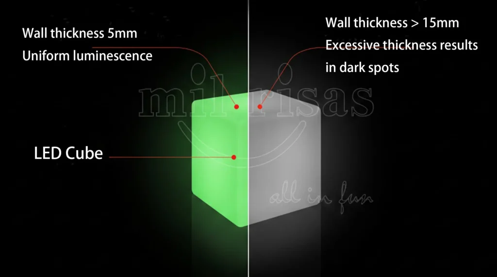
Wall Thickness Control (2–15 mm) ⭐⭐
Wall thickness depends on powder weight and heating time, not mold size.
Adding more powder increases uniform thickness.
Corners thicken naturally by around 25%, offering free reinforcement.
Best Practice:
Use 5 mm average walls and about 8 mm near LED channels to balance brightness and durability.
Technical Insight:
Controlled wall thickness ensures strength and visual uniformity.
Thick sections prolong cooling. Thin zones may warp or crack.
Calibrate powder weight per cavity volume for predictable results and even luminous effects.
Embedded Nuts, No Internal Ribs ⭐
All metal inserts (M6–M10) should be added after molding, accurate to ± 0.5 mm.
Internal ribs or columns block powder flow and trap air. They leave voids or weak fusion areas.
Best Practice:
Use surface‑mounted inserts instead of internal supports.
This keeps powder free‑flowing and avoids defects.
Technical Insight:
Surface nuts improve distribution and demolding.
They also eliminate thermal mismatch between metal and plastic, improving long‑term stability under load and temperature cycles.
±0.5% Dimensional Accuracy ⭐
Rotational molding runs under low pressure, so dimensions depend on cooling shrinkage, not mold precision.
It’s much more forgiving than injection molding.
Best Practice:
For large furniture, ± 1 cm tolerance (≈ ± 0.5%) is acceptable.
Organic curves can form accurately without precision steel tooling.
Technical Insight:
The material shrinks freely inside the mold, absorbing minor deviations.
With consistent heating and wall control, the process still achieves strong, stable parts despite broad tolerances.
Dual Process LOGO Customization ⭐
Rotational molding supports two branding methods based on production volume.
Steel Insert — Mass Production
A machined insert fixed into the mold forms a permanent embossed or debossed LOGO.
It’s durable, repeatable, and ideal for 300 pcs or more.
CNC Engraving — Low Volume
For small or changing designs, engrave logos after molding.
This achieves sharp detail with minimal setup.
Technical Insight:
Steel inserts survive hundreds of cycles and ensure a consistent surface finish.
CNC engraving offers flexibility for custom runs.
Choose based on batch size and visual precision.
LED Channel Golden Specs ⭐
LED channels require a balanced structure and lighting.
Use channels 8–12 mm deep × 15–22 mm wide × R2 fillet.
Reasoning:
This range fits most IP65 LED strips and gives space for sealing, wiring, and expansion.
The R2 corner reduces stress and improves material flow.
Best Practice:
Aim for 10 mm depth × 18 mm width to achieve even light diffusion.
Adjust based on wall thickness or brightness needs.
Technical Insight:
Well‑designed channels prevent hot spots and shadows.
They keep LED strips secure while resisting vibration and heat.
Overly narrow or sharp channels slow powder flow and reduce surface strength.
Rotomolding vs Traditional Processes
| Application Scene | Rotomolding Advantage | Injection Molding | Blow Molding Limitation |
| Glowing Swing | One‑piece structure, seamless finish | Requires split parts | Seams may leak |
| Complex Channel Stool | Integrated hollow channels | Complicated post‑machining | Nearly impossible |
| 50 cm Small Stool | Fully feasible with consistent walls | Faster cycle time | Walls often too thin |
| IP65 Waterproof Table | Seamless and watertight | Walls are often too thin | Likely to seep at seams |
Observation: Rotational molding excels in seamless, hollow, and waterproof builds.
Injection molding suits thin parts with tight tolerances, while blow molding struggles with thick or complex LED channels.
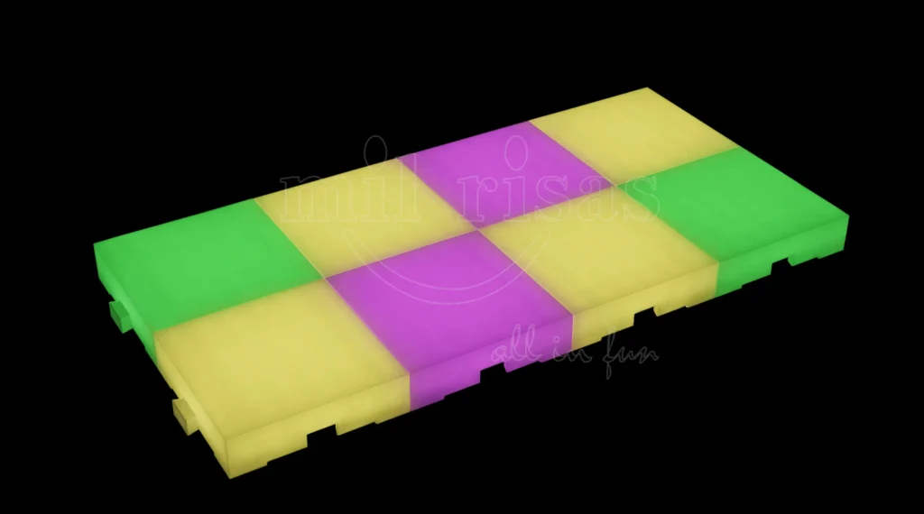
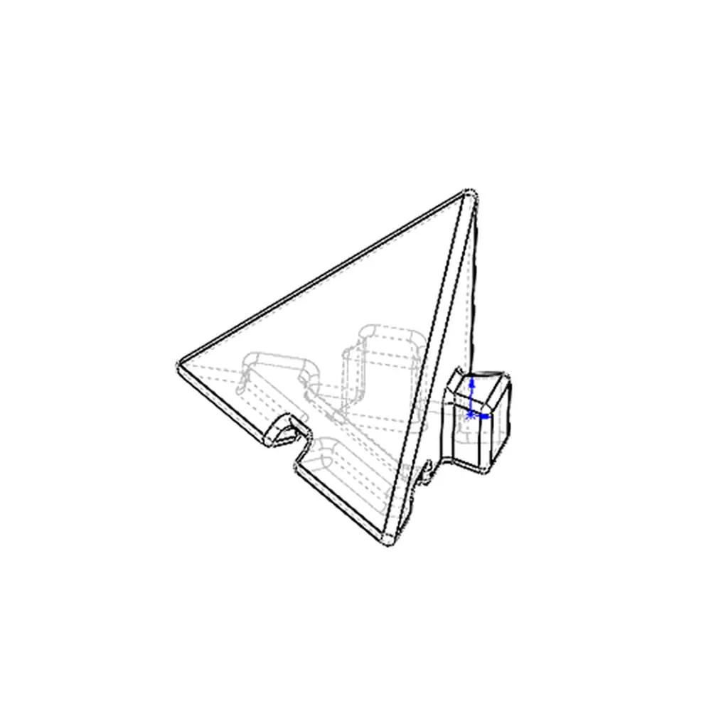
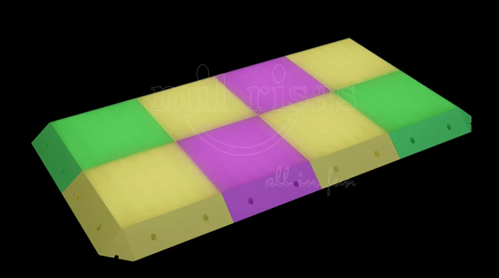
Real-World Design Evolution: Beveled LED Dance Floor Panel
Case Study: Square LED Dance Floor Lights With Buckles
Based on actual prototypes developed for enhanced stability and modular assembly
Scheme A – Initial Bevel Addition
Added sloped bevel edge for smoother transitions between panels
Included small triangular fillets at corners for visual continuity
Challenge: Edge stability is low under foot traffic; relied on the friction fit only
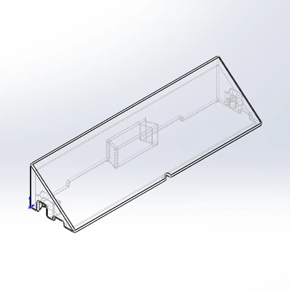
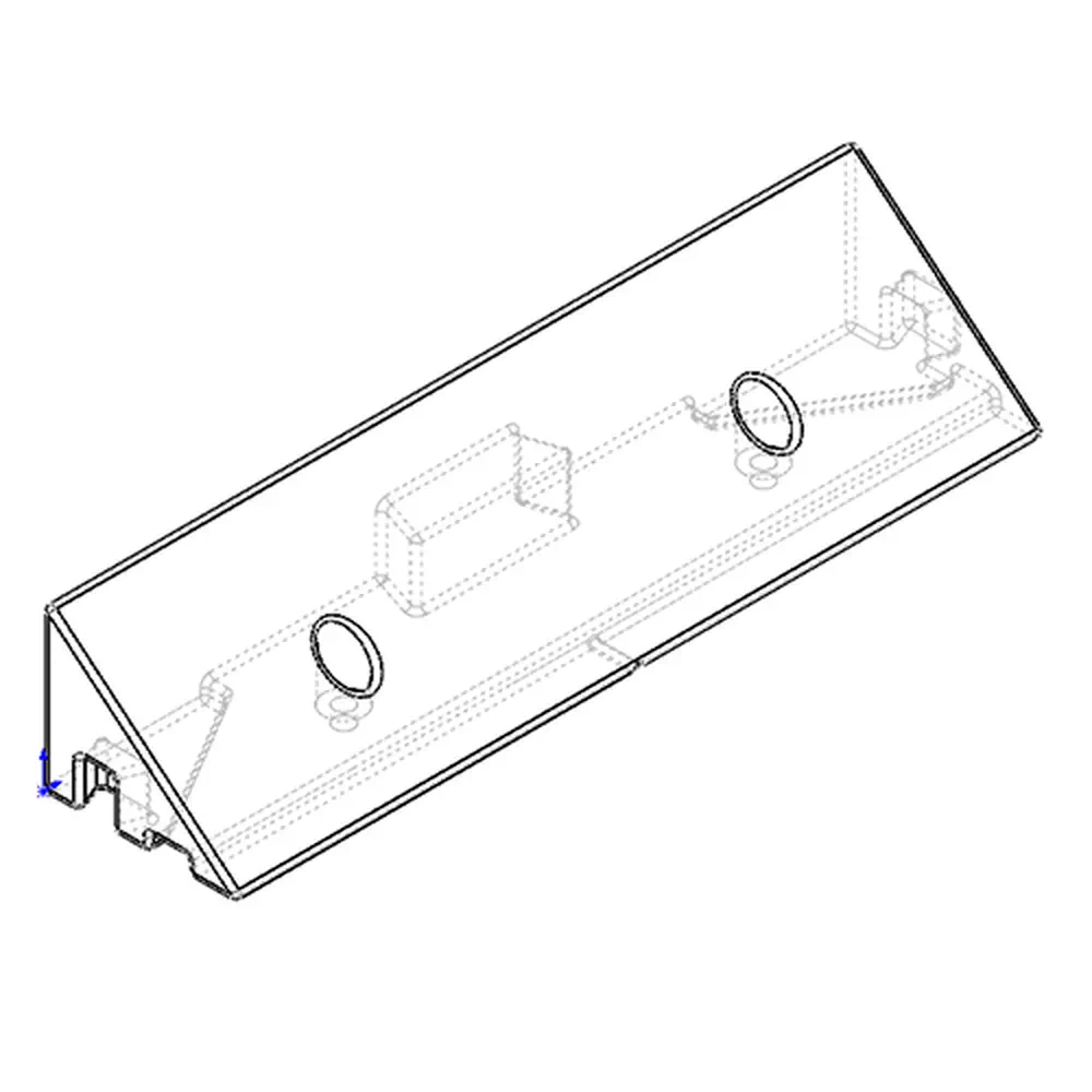
Scheme B – Locking Hole Optimization
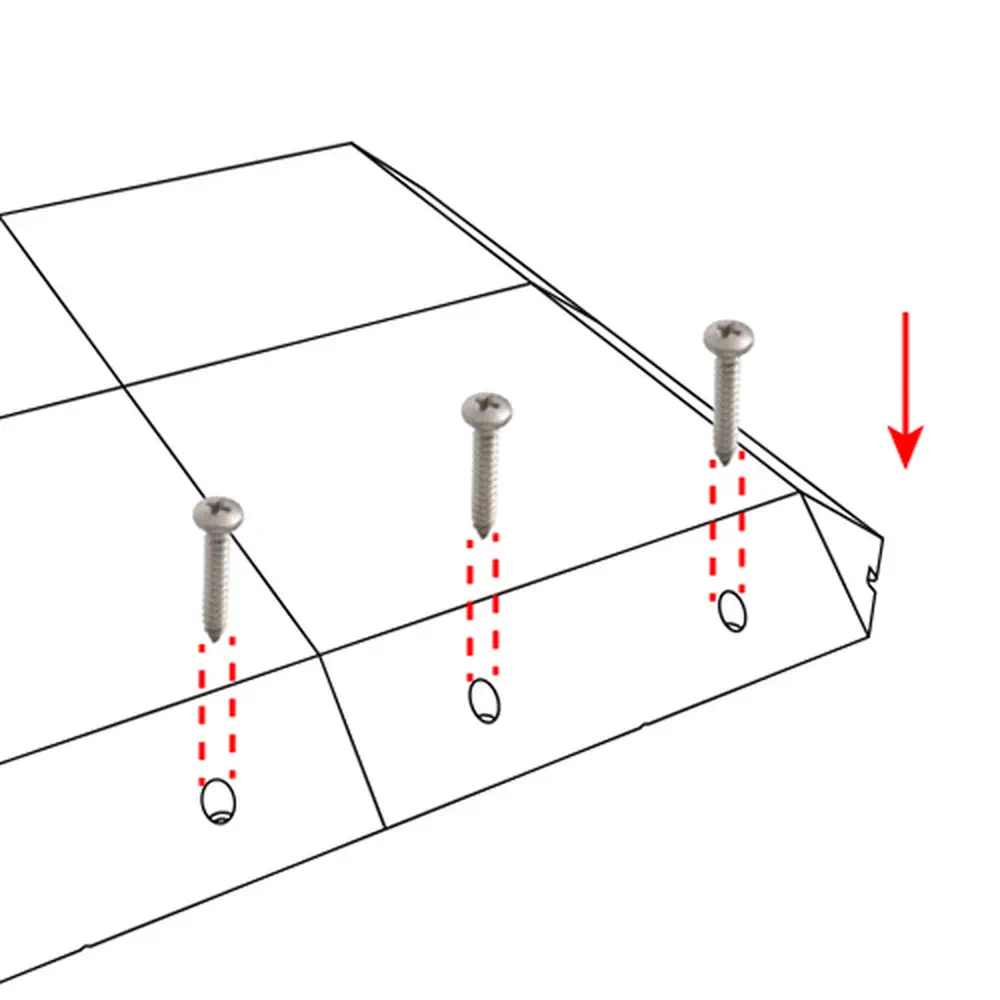
Added two mounting holes on each beveled face for the screw option
Dual-use design: Lock with screws for permanent installs, or leave open for tool-free setup
Result: 3x better edge grip while maintaining seamless appearance
Key Improvements Delivered:
| Aspect | Scheme A | Scheme B |
| Edge Stability | Friction only | Screw-optional |
| Assembly Speed | Moderate | Fast (tool-free option) |
| Floor Tolerance | Limited | Handles uneven surfaces |
| Rotomolding Compatibility | ✅ | ✅ (post-processed holes) |
Technical Validation:
Holes positioned to avoid powder flow obstruction during molding
Bevel angle optimized for IP65 sealing between panels
Maintains uniform 5mm wall thickness across sloped surfaces
FAQs
Q1: What does ±0.5% mean in practice?
2m sofa: ±1cm acceptable (±0.5%). 5x more forgiving than injection.
Q2: Why no internal ribs?
Powder can’t fill closed spaces. Creates voids. Use surface nuts.
Q3: How to control wall thickness?
Powder weight sets base (450g/L=5mm). Oven time fine-tunes ±1-2mm.
Q4: Powder-to-thickness formula?
450g powder/liter = 5mm average wall. Corners +25% naturally.
Ready for Signature Glow Furniture?
Continue our technical series:
Rotational Molding Materials →
Rotational Molding Mold Design →
Rotational Molding Post-Processing →
Rotational Molding Applications →